Fitting the Boot Mount Spare
The boot mounted spare, or ‘Continental Touring Kit’ as dealers called it, is an iconic part of the Rover P6’s look, and one of the few saloon cars to carry a spare wheel so prominently on the outside. It was Rover’s solution to the impractically small and oddly-shaped boot space afforded by the Rover P6. How to fit this kit is an common question, so in this article we explain the parts you will need to source and how to go about fitting it to your car.
The shape and amount of space in the boot of the Rover P6 is one area that can lead to frustration, and arranging luggage prior to weekend trip. Add to that some of our modern day needs like a cool box and space suddenly diminishes. Part of the reason for poor space lies in some of the technical advancements of the Rover design. The DeDion tube sits behind the rear axle encroaching into what could be valuable boot space, and the petrol tank is mounted behind the rear seats (to minimize damage and therefore fire risk in a crash) creating a deep but not very long luggage compartment. With the spare wheel mounted in its standard position, space is at a premium, so mounting it on the outside is a very practical solution when touring.
What parts do I need?
Our usual P6 suppliers will probably be able to supply most/all of the parts required, and they do occasionally come up on eBay as well. However sourcing from the latter won’t always yield everything you need in one go and sourcing might take some patience and time.
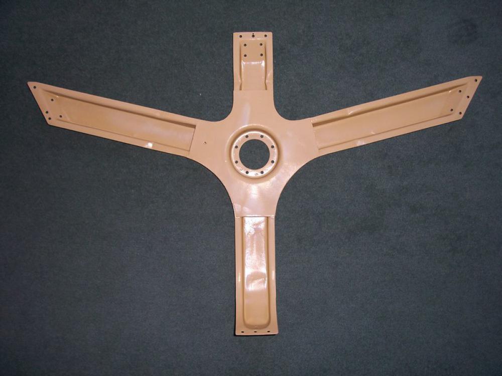
Stiffener or “The Spider Brace”
The spare wheel on an aluminium boot lid is very heavy. Rover devised new bracing to overcome this weight and prevent flexing. Fitting this will require removal of the existing aluminium single bar brace. You will also need suitably size pop rivets, a rivet gun and a hole saw.
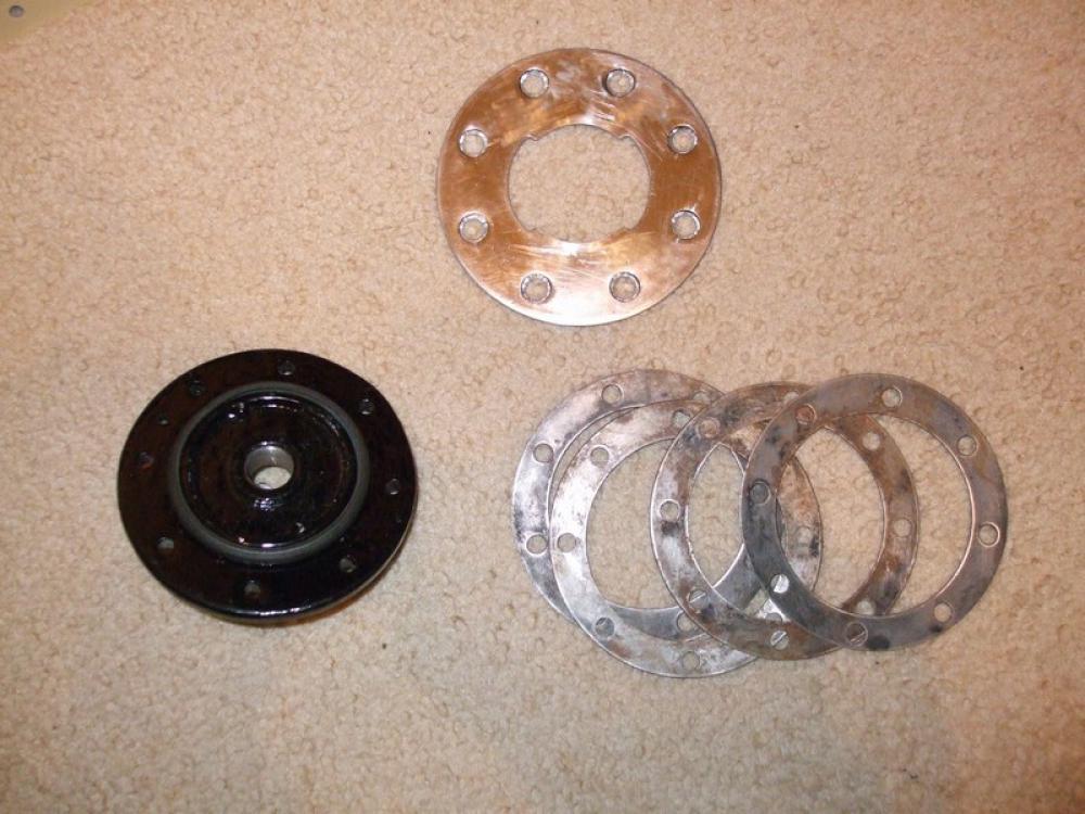
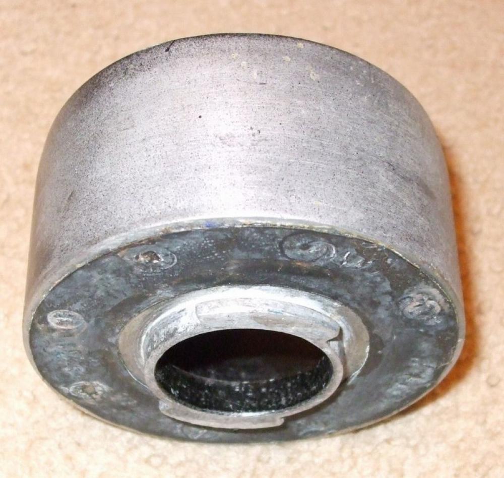
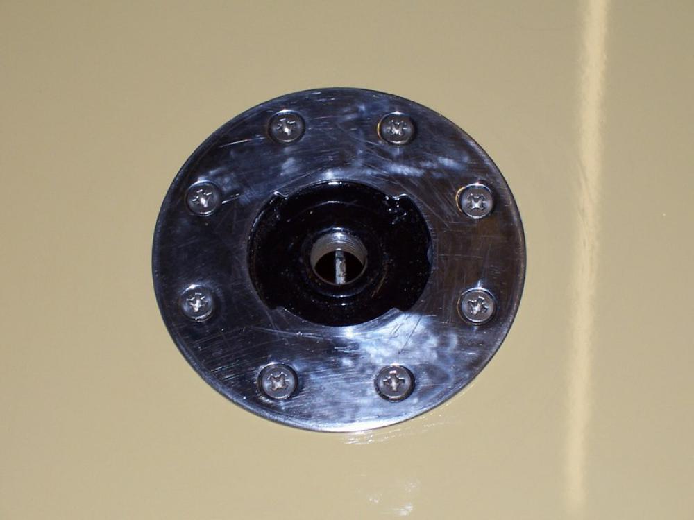
Mounting Hub
The mounting hub fits to the brace and the boot lid, along with the mounting hub, you need thick and thin shims, a rubber seal (mounting hub to underneath the boot lid) and a wearing plate for the top of the boot lid. The finisher is slotted for a bayonet fitting. You will also need eight 10 UNF inch-long bolts and nyloc nuts (or close metric equivalent).
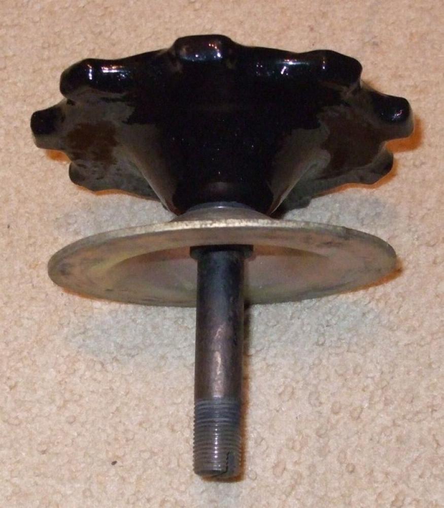
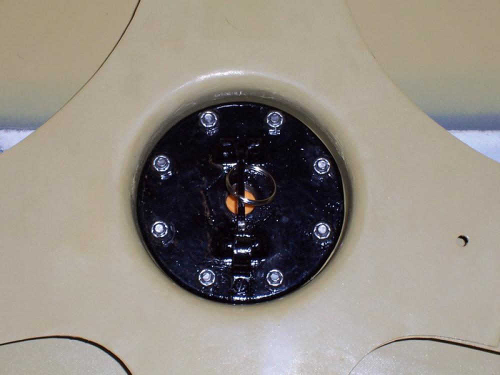
Locking Wheel and Locating Cup
The knurled locking wheel complete with clamping plate and rubber collar (to keep the clamping plate in place) and locating cup is the mechanism to fix the spare wheel to the mounting hub. Note that the clamping plate and locating cup are different for the different P6 wheels. The vast majority found today are for steel wheels, but different items were manufactured for Rostyles and wire wheels.
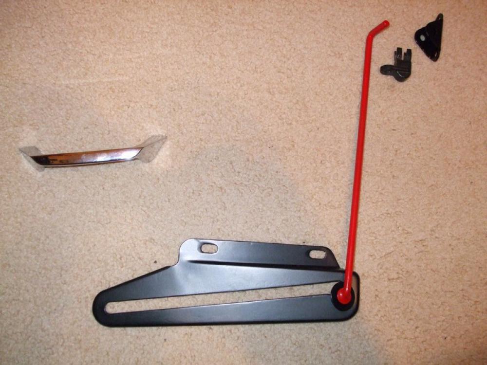
Boot Prop
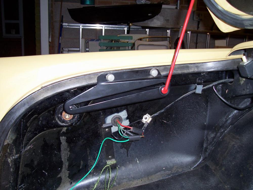
 The torsion springs located under the rear decker are no match for keeping the weight of the spare wheel up when the boot is open, so a prop and fittings were supplied to hold the boot lid up. When fitted, the boot lid does not open as far as normal to prevent the wheel from getting to close to the rear screen, so you have to be careful not to scrape your head on the boot lock! This prop assembly consists of a red boot prop (they were always red), mounting bracket, pivot bracket and nylon locking device. To lift the boot lid, you will also need a handle. The boot mount handle was identical to the Series 1 door handle fitted upside down. In addition (not shown here) there was also a stowage bracket, very similar to the pivot bracket but slightly smaller. The stowage bracket was fitted to the left hand side gusset, you may be able to see holes in the gusset showing where to fit the stowage bracket.
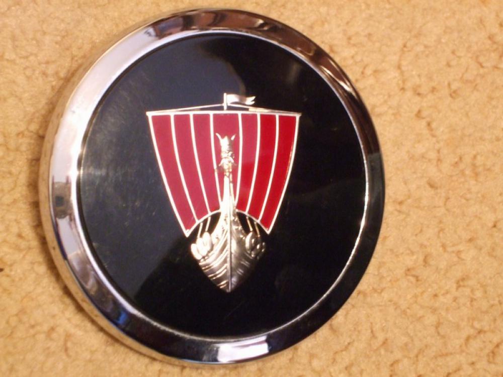
Boot Lid Rover Motif
For those occasions when you want to leave the spare wheel in the boot, you will need a boot motif that seals the hole and locks into place in the mounting hub. When the boot mount is being used for the spare wheel, the motif can be stored on the knurled locking wheel. Note however once on the locking wheel it can easily be stolen.
Support Arm for Spare Wheel
This additional mechanism replaced the normal bracket in the boot for mounting the spare wheel in the standard upright position. It enables you to do away with the existing bracket and use the locating cup and knurled locking wheel to secure the wheel instead. It has the same bayonet fitting as the wearing plate thereby making the boot mount fittings dual purpose. When the spare wheel is fitted to the boot lid, this support arm can be rotated 90 degrees to hide it behind the boot liner and out of the way of your luggage. Note the support arm will not fit suffix A Rover 2000s without modification to the base unit.
Fitting Boot Lid Mounting
Contrary to Rover instructions at the time, which stated drilling all the holes in the boot lid prior to fitting the spider brace, we would suggest fitting the spider brace first, to ensure you get them in the right place.
Open the boot, and remove the boot lid by removing the hinge cover plates to expose the two bolts. This is a two man operation to ensure that once the bolts are undone, the boot lid is fully supported and not leaning on the hinges as this can put pressure on the lid causing the metal to flex and damage your paint work. With the boot lid off, lay it down on the floor (suitably protected), upside down. Remove the liner and carefully drill out the spot welds securing the aluminium brace. Drill slowly with light pressure so as not to damage the outer skin if the drill goes right through
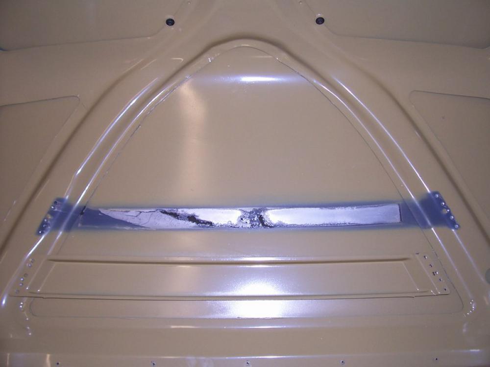
Mark a centre line down the boot lid, and place the spider brace in place and ensure that it sits dead centre. You may need to provide some encouragement with a hammer and/or the vice to get the best fit. Carefully mark through one of the fixing holes in the brace and drill. If your drill moved, and you’re slightly out, you can elongate this hole to keep the spider brace central and pop rivet it. Do the same on the opposite side, and with the brace firmly fixed in place, drill the remaining holes and pop rivet it in place.

With the spider brace fitted, drill out the 8 mounting hub fixing holes through the spider brace. Measure for the centre of the larger hole for the mounting hub and drill a small pilot hole. To reduce the damage on the outside of the boot lid, drilling the large hole is best done from the top of the boot lid. Now take one of the thick shims and with 3 bolts, fix it to the outside of the boot lid. This will prevent your drill from slipping across the boot lid and damaging your paintwork while you drill a ~54mm hole with a holesaw. The holesaw makes a very poor finish, but this is easily tidied up with a file or rotary tool.
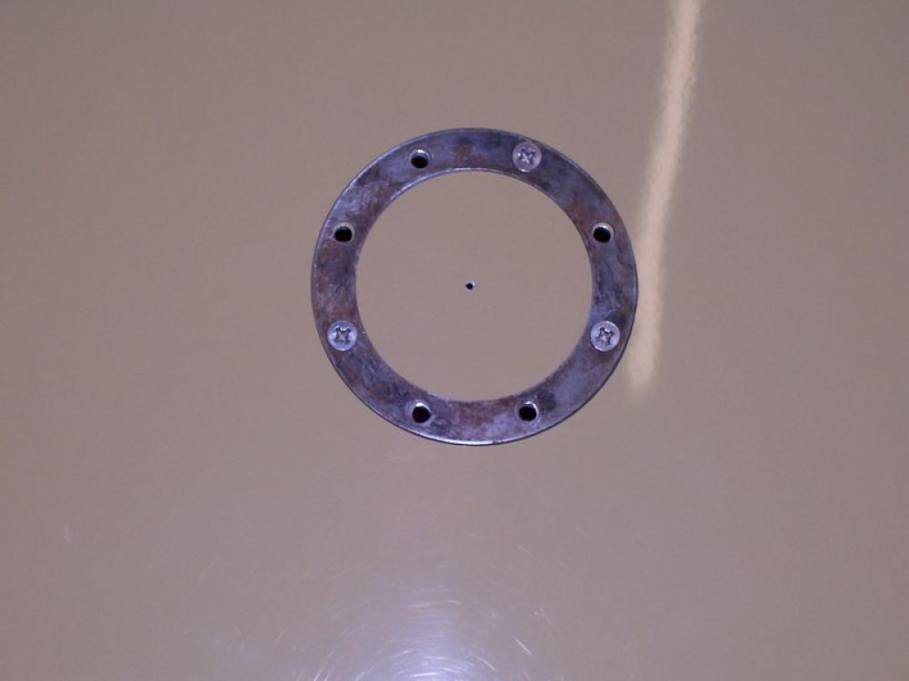
With the hole drilled, refit the boot liner and mark the outline of the hole on the boot liner. This is to enable you to operate the locking mechanism of the mounting hub.
Slide two thin and one thick shims between the spider brace and the boot lid, and one thick shim between the spider brace and the mounting hub. Fit the mounting hub to the boot lid with the locking hinge towards the back. The wearing plate has the locating slots in a left/right orientation. Fit the locating cup onto the boot lid and check operation, it should turn freely and there should be no distortion in the boot lid. If you have any problems, you should try different shimming until you are satisfied with the operation.
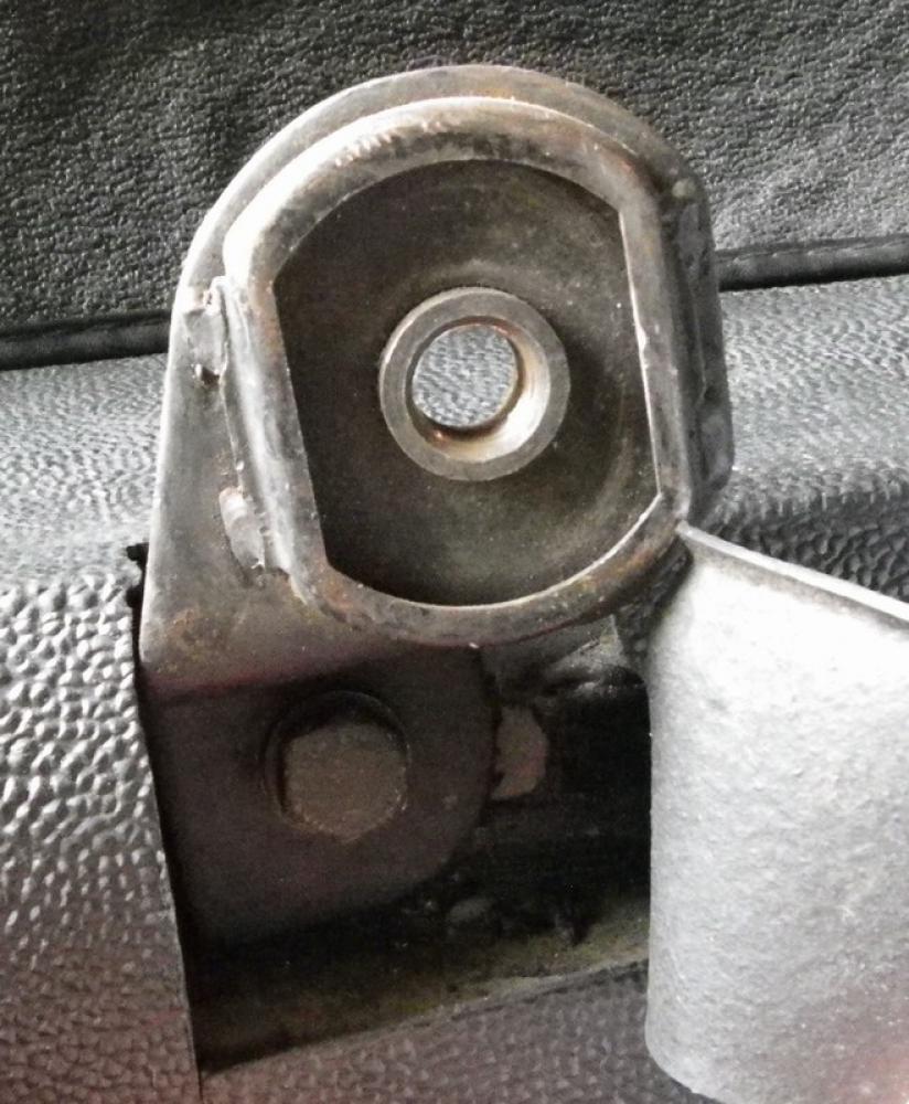
Fitting Mounting Bracket
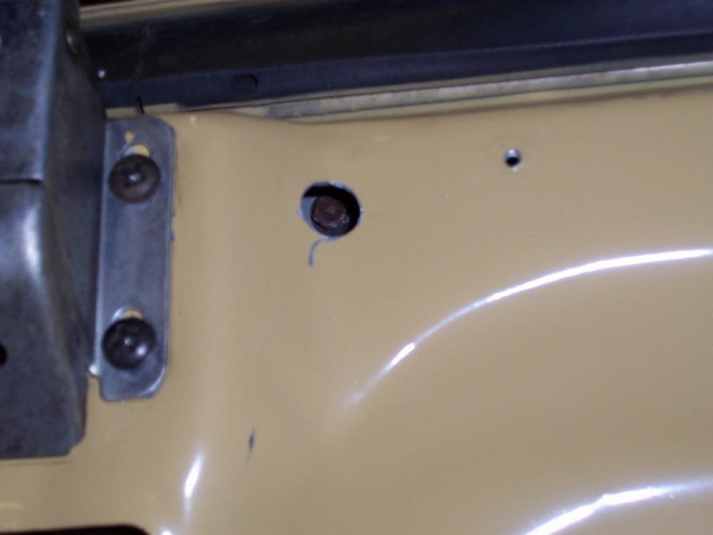
The mounting bracket is bolted to the near side boot drain channel. Measure from the centre of the near side wing fixing bolt 219mm to the drain channel, mark and drill the bolt fixing. Temporarily bolt up the mounting bracket front fixing and use the bracket as a template to mark and drill the rear fixing. Now bolt up the mounting bracket permenantly using some sealant to prevent water ingress to the boot.
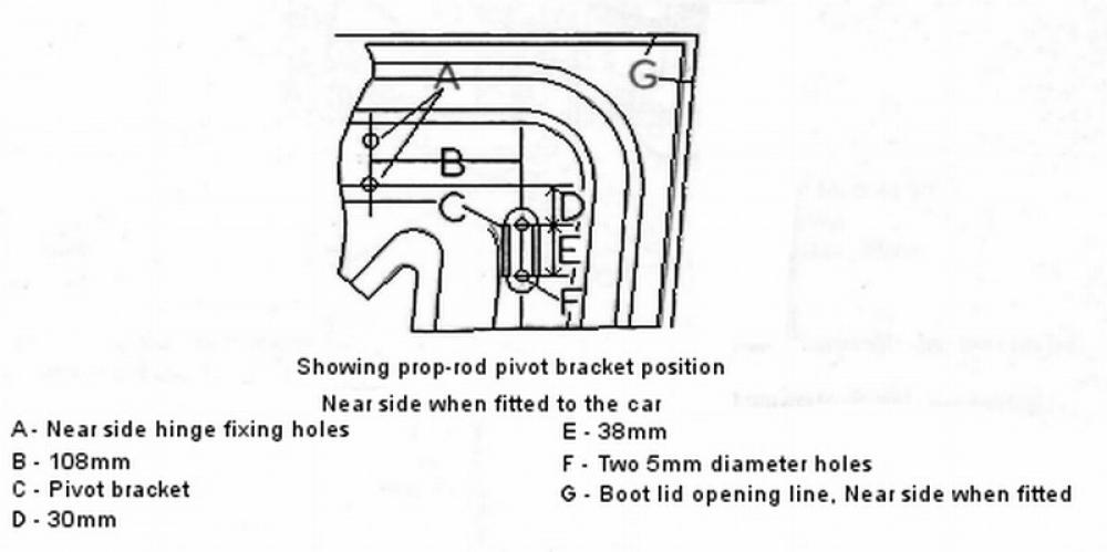
The pivot bracket must now be fixed to the boot lid. Rover supplied the dimensions for the location of this bracket in relation to the left hand hinge fixing holes as shown in this diagram. You might find it easier to make a template of this on a sheet of paper to scale to find the correct place.
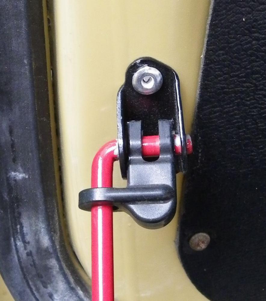
Using the pivot bracket as a template, mark, drill and pop rivet the pivot bracket to the boot lid.
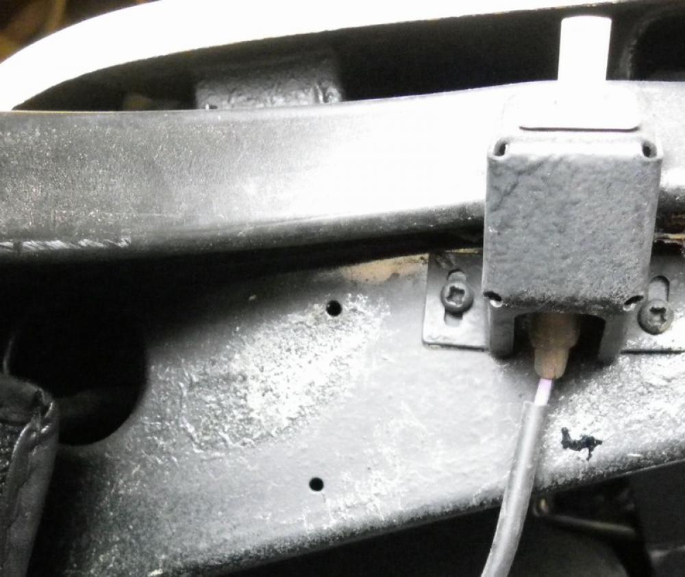
Fitting Boot Lid Handle
The handle should sit 50mm up from the bottom edge of the boot lid. Measure the distance between the bolts, mark a centre line down from the boot lock and drill the fixing holes 7/32” diameter. On the inside of the boot lid, measure 57mm up from the bottom edge of the boot lid and carefully drill two holes about 19mm diameter, exactly opposite the previous handle fitting holes. These holes need to be large enough to get your thinnest socket through to attach the handle. Remember to fit the handle upside down to series 1 doors. A little blue tack in the socket will help keep the nut in position and not fall out of your socket.
With the job complete, refit the boot lid to the car, again a two man job to prevent the boot lid resting on the hinges, bending the metal and ruining your paintwork. Attach the prop rod to the pivot bracket and secure with the nylon locking device.
Written for Driving Force Magazine by Brian Humphreys